
Simon Lab · the bottom-up method
Your AI agent does not need another chat window. It needs a plant to work in.
Simon Lab is the production environment in which an AI agent designs a complete chemical installation, from the physics of the process to the drawings a contractor can build from. Layer by layer, under rules that keep the work complete and in the right order.
Scroll to build the plant
Chapter 1
From a chat to an environment
Most engineers know AI as a chat window. Here is how a chat becomes an AI agent, what an AI agent does on a plant project without an environment, and what Simon Lab gives it.
Chat
A chat answers, one document at a time
Ask a chat to size a pump and it hands you the sizing documentation. Open a new chat to check the strength of the agitator shaft and you get another document, which knows nothing about the first. A third question, a third document.
Every answer stands alone and has nothing in common with the one before. Matching the answers, checking them and carrying them into the project is still your job.
Your AI agent
An AI agent is a chat that was given tools
The AI agent was built to answer exactly that problem. At its heart is the same chat, the intelligence. Around it, it gets tools, a plan, files and checks, and it works in a loop until the task is done.
Codex, Claude Code, Grok Build and Google Antigravity are AI agents of this kind.
Our experience
Let loose on a project, it fires documents
An AI agent works on files, the way a programmer works in a repository. Let loose on a plant project, it builds an environment of its own, but it does not know the right standard, and every topic starts from an empty folder. Then it fires like a machine gun: series after series of documents, and the series collide, because nobody defined the standards.
The advanced tools do not exist. And when you started this weekend project, you did not think it would turn into a year of optimizing a CFD solver and rendering CAD geometry on a worn-out laptop.
Simon Lab
Bring your own AI agent
Simon Lab lets you bring your own AI agent: BYOA (bring your own agent). Simon Lab gives it the environment: every part of the project has its place in a layer, and every layer is built on the one below. The AI agent starts with the specification in CapacityIndex and builds the process in ProcessView; when the process shows that the specification needs a change, it goes back, and both get a new revision.
Iterations
Every revision tested, the project released together
A change in the process rebuilds what depends on it: the machine, the cabinet, the 3D model and the site. Every document is checked again on every revision. When all of it passes, the project moves from beta to version 1.0 in every application.
Behind the layers are engineering applications, one per discipline, rules of good engineering practice written down as checks, and the compute that real verification needs (CFD, FEM, rendering), on our own machines.
Chapter 2
The AI agent reads code, the engineer sees the plant
The AI agent proposes, the engineer approves. The AI agent reads code and does not need a screen. The engineer needs to see the work to decide, and Simon Lab provides that interface: one model, shown to each of them in their own language.
AI agent excerpt
{
  "equipment": ["TK101", "P101"],
  "junctions": ["J101", "J103"],
  "pipes": [
    "SEG-TK101-D1-HV101-N1",
    "SEG-HV101-N2-WP103-N1",
    "SEG-WP103-N2-J103-N1",
    "SEG-J103-N2-P101-N1",
    "SEG-P101-N2-J101-N1",
    "SEG-J101-N3-XV102-N1",
    "SEG-XV102-N2-TK101-C1"
  ],
  "valves": ["HV101", "XV102"],
  "instruments": ["LT101", "PT101", "TT101"]
}
Engineer
AI agent excerpt
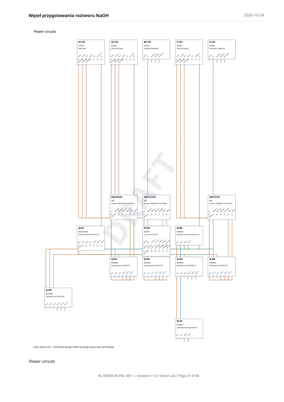
Q-P101-L1        Q-P101:L1-OUT   →  DRV:P101:L1            4 mm²
Q-P101-L2        Q-P101:L2-OUT   →  DRV:P101:L2            4 mm²
Q-P101-L3        Q-P101:L3-OUT   →  DRV:P101:L3            4 mm²
M-P101-U         DRV:P101:U      →  P-101:MOTOR:U
M-P101-V         DRV:P101:V      →  P-101:MOTOR:V
M-P101-W         DRV:P101:W      →  P-101:MOTOR:W
PE:DRV:P101      PE101:DRV:P101  →  DRV:P101:PE            2.5 mm²
PE:PV:P101       PE101:PV:P101   →  P-101:PE
IO:XV102.open    DIO1:DI14       →  XIO-XV102.open-S:IN    1.5 mm²
IO:XV102.closed  DIO2:DI1        →  XIO-XV102.closed-S:IN  1.5 mm²
Engineer
AI agent
Engineer
ProcessView
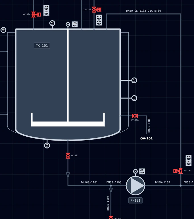
A data structure, or a P&ID
To the AI agent, the process is structured data: every tank, nozzle, line and instrument an object with its connections. The engineer sees the same model as a P&ID.
IonGrid
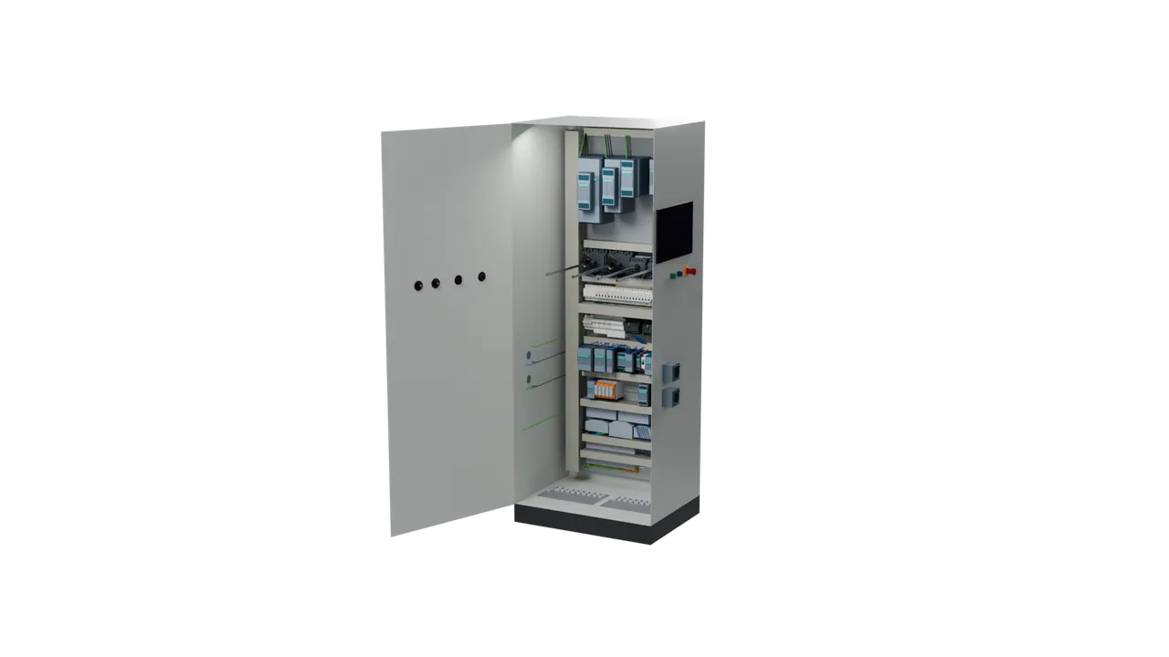
A netlist, or a cabinet
The AI agent does not need a render of the cabinet. It reads a netlist: devices, terminals, wires and signals. The engineer sees the cabinet in 3D, part by part, as it will be built.
PlantMesh
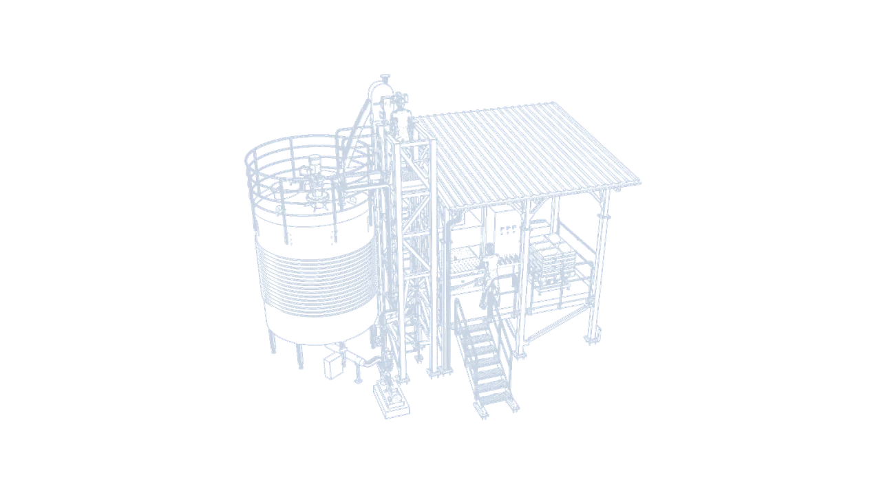
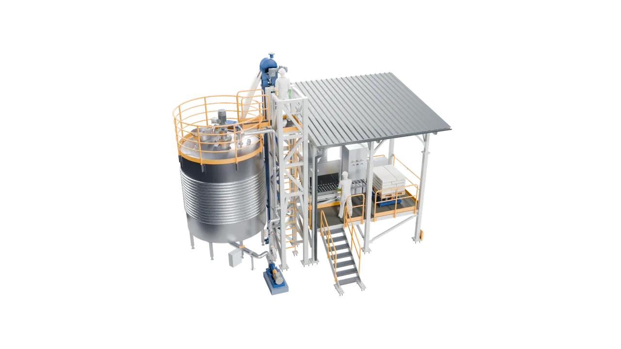
Edges and coordinates, or the unit itself
In PlantMesh the AI agent works with the geometry, its edges and coordinates. The engineer sees the unit rendered, with its steel, its piping and the people who will operate it.
Iterations this fast let the engineer work with the project like modelling clay, without waiting weeks and asking for a new revision of the support structure. A direction can be seen before it is chosen, so the engineer knows whether it is worth taking.
The engineer works more like an artisan than like a part of a corporate machine, free of the coordination between disciplines, and can design installations to be proud of: the speed of iteration brings a quality that until now was out of reach.
Chapter 3
Bottom-up: physics first, budget and timeline last
Projects usually start from a budget and a timeline, set by someone who does not yet know the physics they depend on. Starting with the physics lowers the effort it takes to begin a project on the right foundation, instead of on a misguided customer assumption that began as an offer prepared in a few hours.
Conventional projects are built top-down from documents, and every discipline patches what the previous one assumed. Bottom-up, nothing is drawn that has not been decided below it.
One project
A project is a stack of decisions
Seen from outside, a plant project is one dense block of information. Inside, it has layers: what the plant must deliver, how the process runs, what the machines and cabinets are, how they fit together, where they stand.
Six layers
Each layer is an application
CapacityIndex holds scope, capacity and economics. ProcessView holds the process and its control. MechGraph and IonGrid design machines and control cabinets in parallel. PlantMesh assembles the unit in 3D. Architecture places it on its site.
Bottom-up
Every layer reads the one below
The AI agent works upwards. Each layer consumes what was decided underneath it and adds detail of its own, so a change to the specification travels up through the process, the machines and the drawings instead of being discovered on site.
Input
Documents are also an input
Whatever a project starts from goes into CapacityIndex: drawings in DXF, models in STEP, specifications in PDF and DOCX, data in XML. It takes in the mishmash and can hand one back, but inside, everything sits in the Simon Lab structure.
Last, not first
Documents are an output
Drawings, datasheets and reports are generated from the layers at the end, not typed in at the start. That is what makes them consistent: they are different views of the same decisions.
Layer 0 · CapacityIndex
Follow the demo project
The rest of this page follows one real project through the stack: a caustic soda dissolution unit, anonymized, designed in the platform and shown with its actual screens and renders.
The brief is the kind an engineer would get on a Monday morning: a plant already makes 5% lye; it needs 30% for a new line, dissolved from flakes delivered in 25 kg bags, in an existing stainless tank, in a free corner of the site.
Bring 5% lye to 30% with NaOH flakes from 25 kg bags, 14.5 m³ batch, max 60 °C in the tank, 40 °C at discharge. Design it with a bottom-up approach, layer by layer, and fit it into a spare area of my plant.
reading NaOH–H₂O thermodynamics…
balancing mass and heat of dissolution…
sizing agitation and cooling duty…
scanning the site for a spare plot…
drafting the design basis…
SPEC · NaOH dissolving unit · draft 1
DESIGN BASIS
product 30 % w/w NaOH · 14.5 m³ per batch
feed 5 % lye + NaOH flakes · 220 × 25 kg bags = 5.5 t per batch
handling bag-dump station · 2 bags/min · 25 kg within manual-handling limits
limits ≤ 60 °C in the tank · 40 °C at discharge
utilities chilled water 7.5 °C · half-pipe cooling jacket
vessel existing stainless tank · retrofit
PHYSICS FIRST
dissolution is exothermic → dosing rate bounded by cooling duty
density and viscosity 5 → 30 % from NaOH–H₂O property models
solids suspension and power number → agitator selection
CAPACITY & ECONOMICS
demand ≥ 60 m³ of lye per week · 3 shifts × 8 h · 7 days
lye fill and pump-out 10 m³/h each → one batch fits one shift
retrofit of the existing tank instead of a new vessel
LAYERS · bottom-up
4 Architecture spare area on site · roads · site plan
3 PlantMesh 3D assembly · isometrics · supports · clashes
2 MechGraph vessel · agitator · shaft · CFD
IonGrid control cabinets · I/O · heat gains
1 ProcessView P&ID · selections · dynamic simulation
0 CapacityIndex scope · capacity · economics ● this spec
OPEN POINTS
flake purity and size distribution: confirm with the supplier
dust extraction and empty-bag handling at the station
The prompt
Plain language in, structure out
The engineer describes the process and its limits (batch size, the 60 °C ceiling in the tank, 40 °C at discharge) and asks for a bottom-up design that fits a spare area of the plant.
Physics first
The specification every layer will read
The AI agent returns a design basis, not a drawing: 30% NaOH in 14.5 m³ batches; 220 bags, 5.5 tonnes of flakes per batch; chilled water at 7.5 °C in a half-pipe jacket; one batch per shift to cover 60 m³ a week. It also states the physics that will bound the design: dissolution is exothermic, so the dosing rate is limited by the cooling duty. And it lists the open points it cannot settle alone.
Nothing goes further until the engineer approves the spec.
An example: every engineer sees the terminal or interface of their own AI agent. The numbers are the demonstration project’s design basis.
Layer 1 · ProcessView
A P&ID that runs
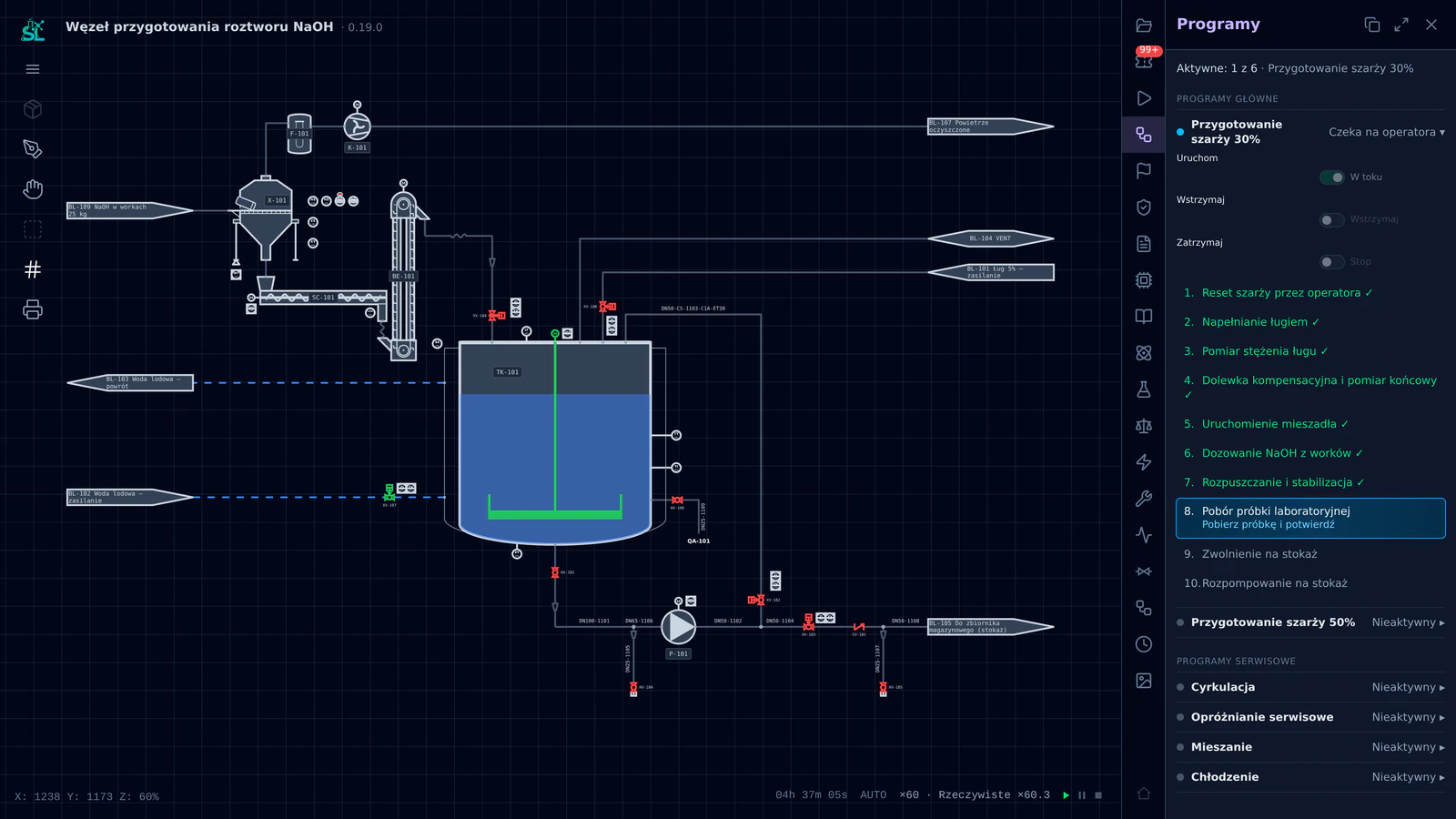
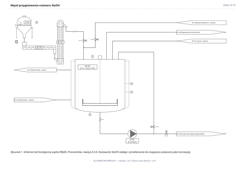
With the specification approved, the AI agent builds the process in ProcessView, not as a picture of a P&ID, but as a model in which every element is an engineering object with a selection behind it.
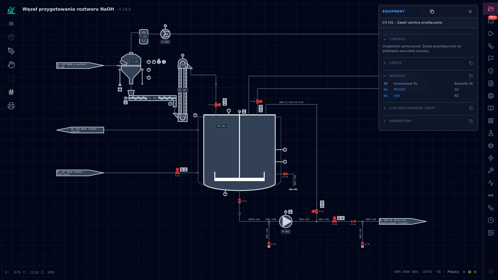
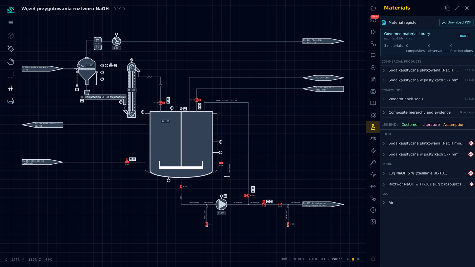
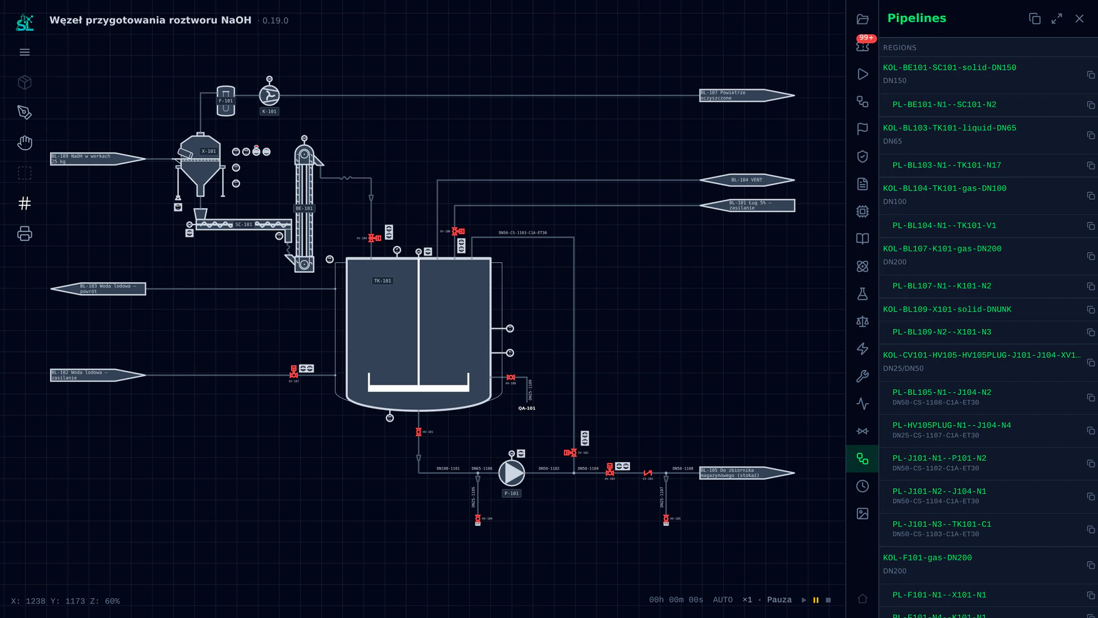
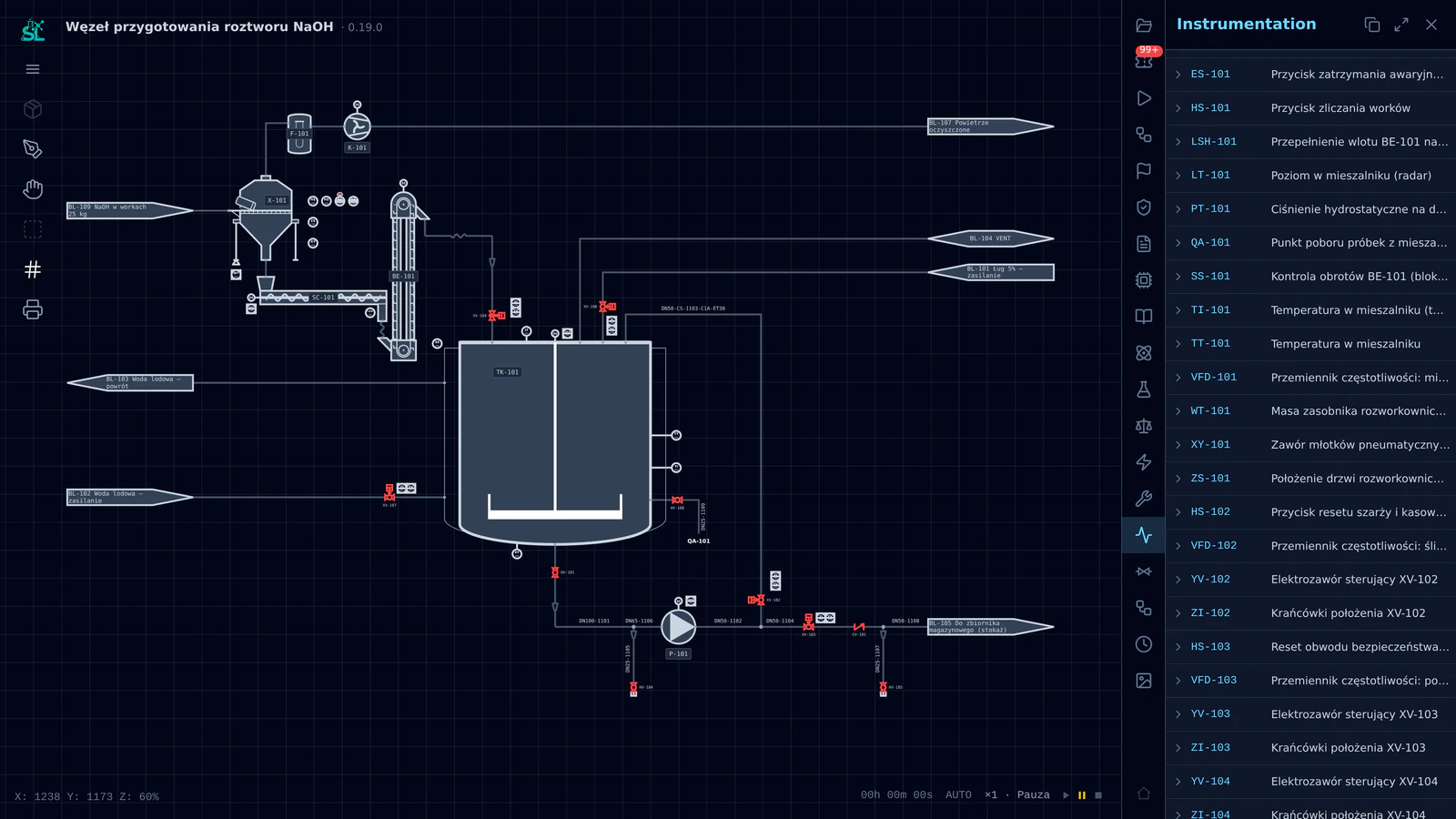
- Filling
- Mixing
- Dosing
- Cooling
Built element by element
Equipment, lines, valves, instruments
The AI agent places the equipment first (the tank, the bag-dump station, the elevator, the pump), then routes the lines between their nozzles, then adds the valves and instruments those lines need. Every kind of device has its class and type; a custom one is created by the AI agent on the spot.

Full selection
Every element carries its decisions
Click any valve and its record opens: what it does, its states, the nozzles it connects, its parameters. Instruments carry their measuring principle and installation; lines carry material and pipe class. These are the guidelines mechanical design, instrumentation and control will read in the next layers.
Registers, not lists
Materials, pipelines, instruments
The same model is also the register: materials with their sources, pipelines with their classes and diameters, every instrument with its loop. Nobody types these tables; they are the schematic, seen as data.
Dynamic simulation
Proven before you buy a single pipe
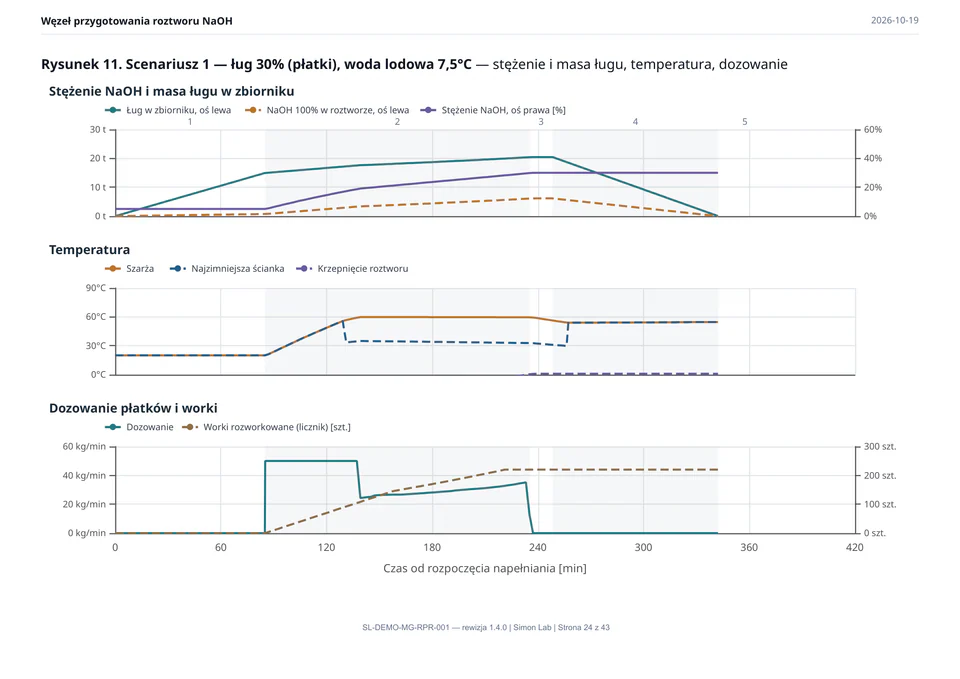
Then the schematic runs. The 30% batch program fills the tank with lye, measures it, starts the agitator and doses the flakes bag by bag while the chilled-water jacket takes the heat of dissolution. Four hours and forty minutes of process, compressed into seconds.
The temperature climbs to the 60 °C setpoint and holds there: the program holds the dosing back whenever the estimated worst-case temperature would cross it. This is the same interlock the real plant will run.

Control
Ready-made programs on an emulated PLC
The batch sequence (reset, fill, measure, top up, start the agitator, dose, dissolve, sample) runs as a control program on an emulated PLC, with operator steps where the real operator will act. When the batch ends, 5.5 tonnes of NaOH have been dosed and the predicted product is 30%.
Layer 2 · MechGraph
The machine, from its own calculations
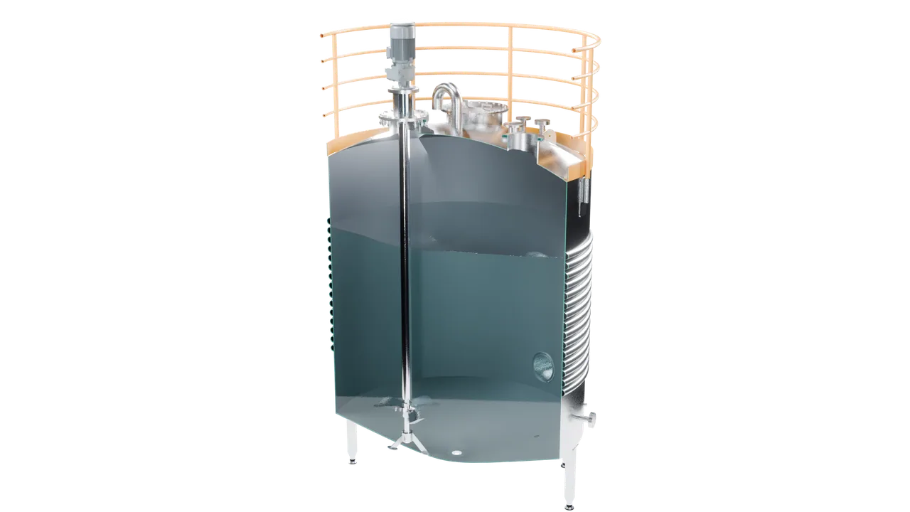
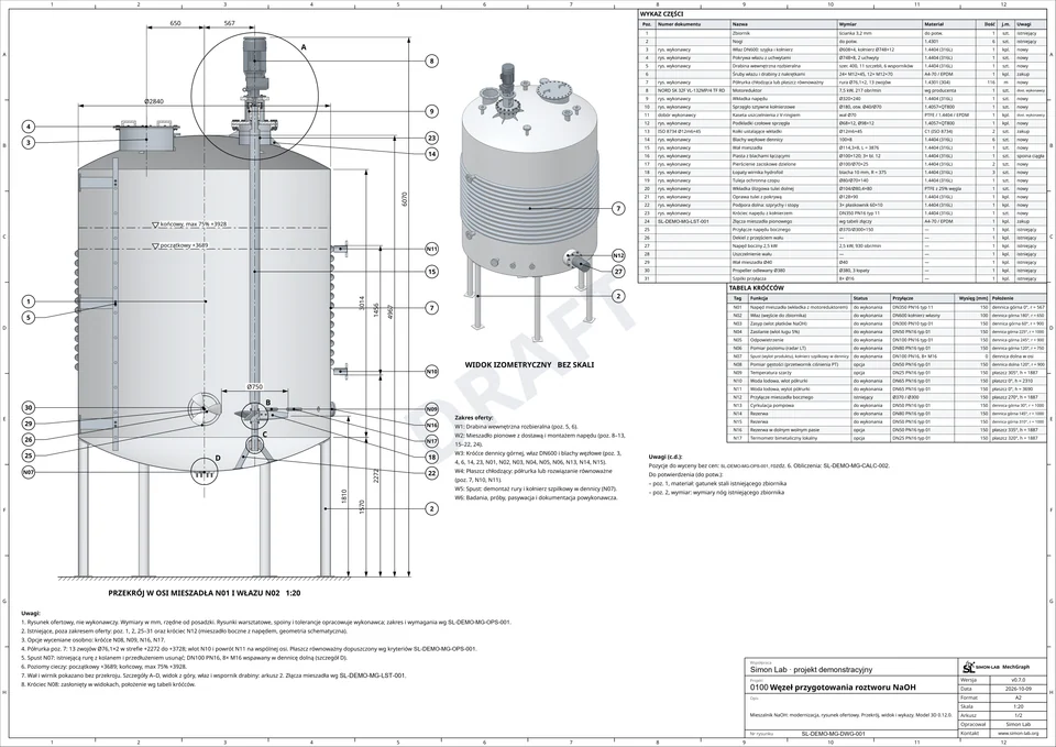
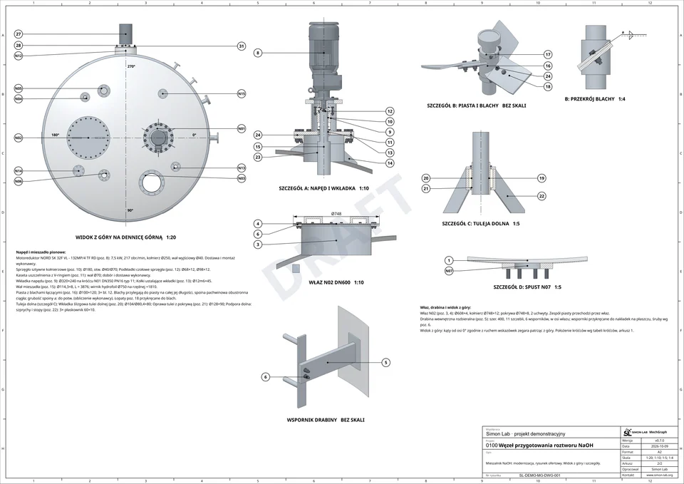
The process now knows what the tank must do. MechGraph turns that into a machine: the existing stainless vessel, its half-pipe jacket, nozzles and platform, and a new agitator sized for the job.
Geometry as a program
Designed from inputs, not drawn
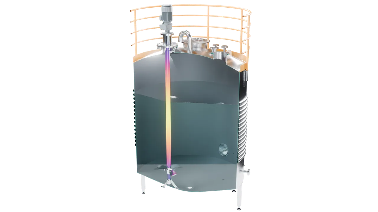
The vessel and agitator are generated from parameters. When the process changes a flow or a temperature, the model, the calculations and the drawings follow from the same source.

Mixing
Power and solids suspension
Cut the vessel open and the design questions appear: how much power the impeller needs, and whether it keeps the flakes suspended until they dissolve instead of letting them settle on the bottom head, while the viscosity, temperature and density of the solution change dynamically.
Mechanics
Shaft deflection, critical speed, strength
A long overhung shaft must not bend into the vessel wall or run near its critical speed; the shell and jacket must carry pressure and temperature to EN 13445. Each check is a calculation with its inputs on record.
Flow
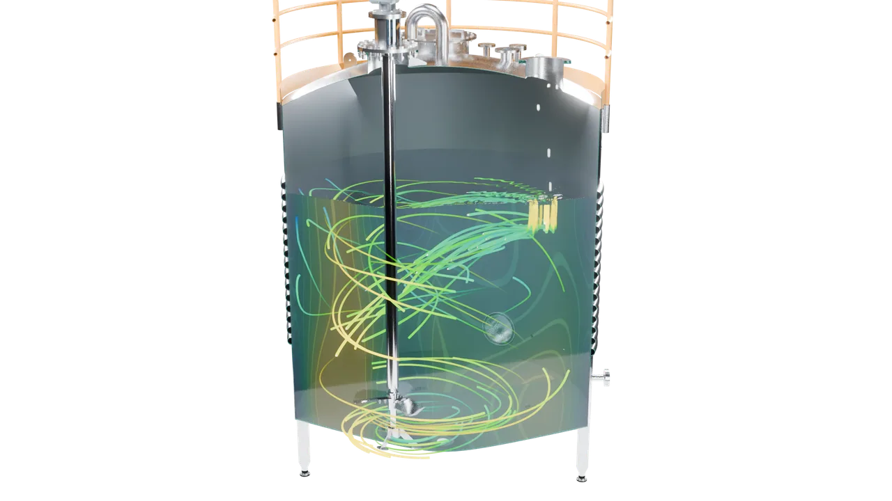
CFD and AI-assisted CFD
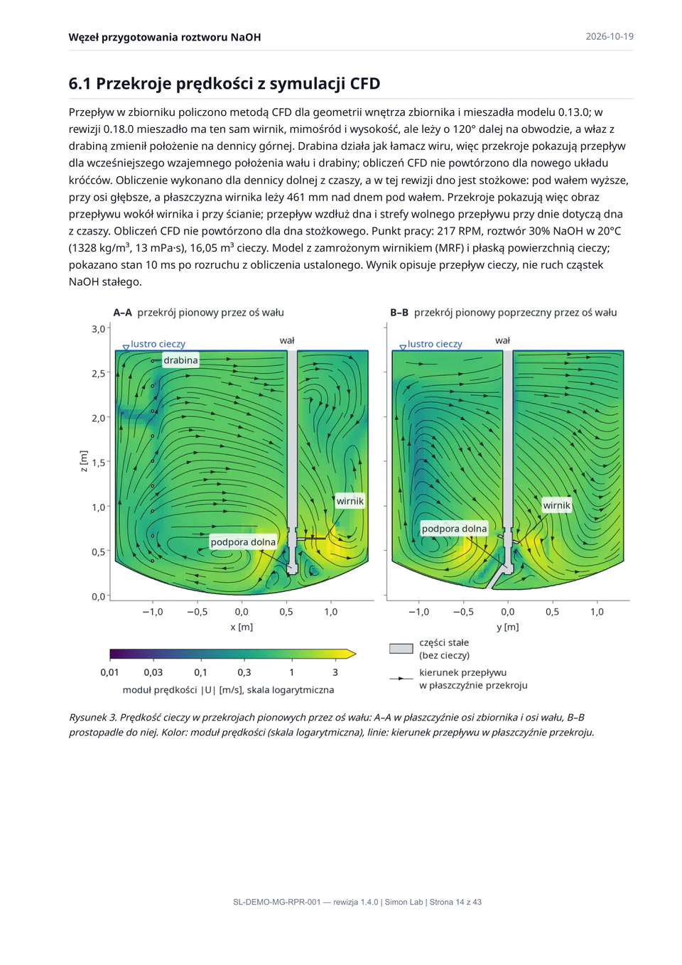
Flow is studied with CFD on our compute nodes. AI-assisted CFD (Walrus, Gemini) lets us verify cases faster and search for the optimal state. Here, flakes enter through the solids nozzle and are carried down by the circulation.
Layer 2 · IonGrid
In parallel: the control cabinet
While the machine is designed, the control logic from ProcessView becomes hardware. IonGrid works on the same level of the stack as MechGraph: two tracks, one set of decisions underneath.
Catalogue components
A real cabinet, part by part
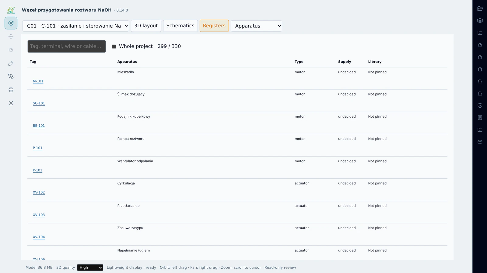
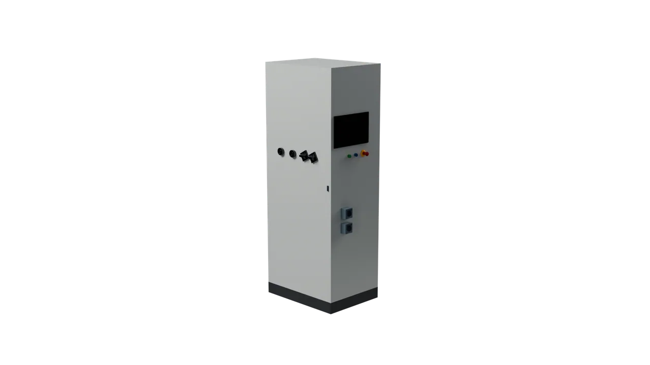
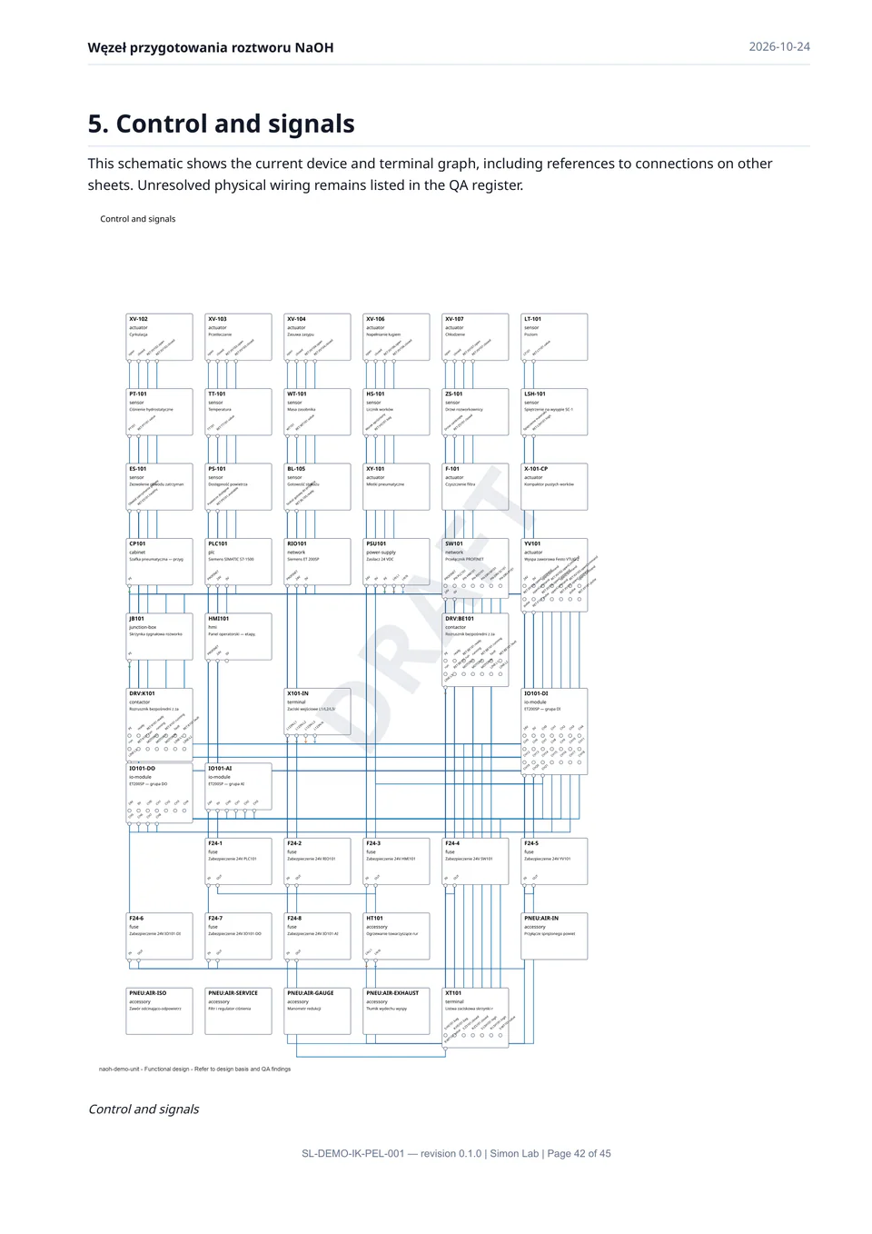
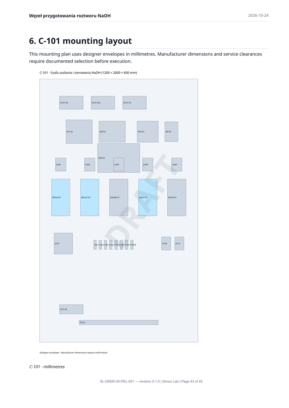
The cabinet is assembled from manufacturers’ models: enclosure and mounting plate, rails and ducts, three variable-speed drives for the process motors, power supplies, the controller with its I/O, terminals and wiring.

Heat gains
What the balance runs on
Every device with a datasheet loss contributes to the cabinet’s heat-gain balance: at least 705 W known so far for this cabinet, most of it from the drives. Pneumatic control stays linked to the P&ID: the controller’s outputs drive the solenoid valves that move the process valves.
Registers
Apparatus and I/O, generated with the cabinet
The apparatus register and the I/O list come out of the same model, signal by signal, ready for the electrician and for procurement.
Layer 3 · PlantMesh
Everything meets in one model
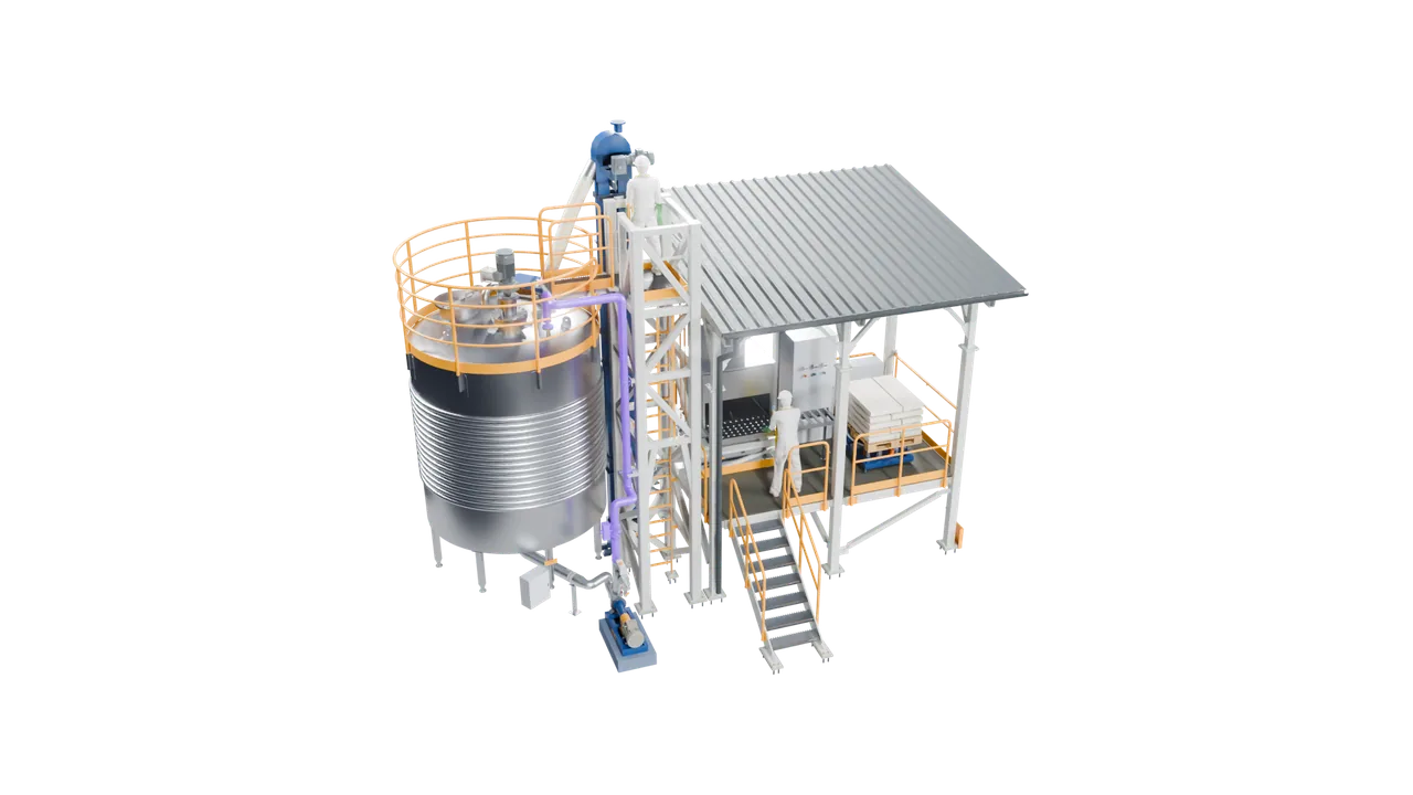
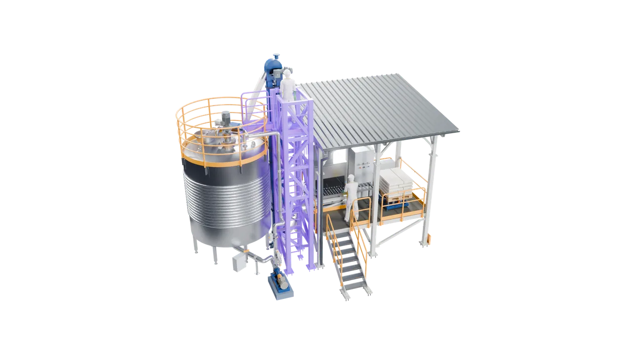
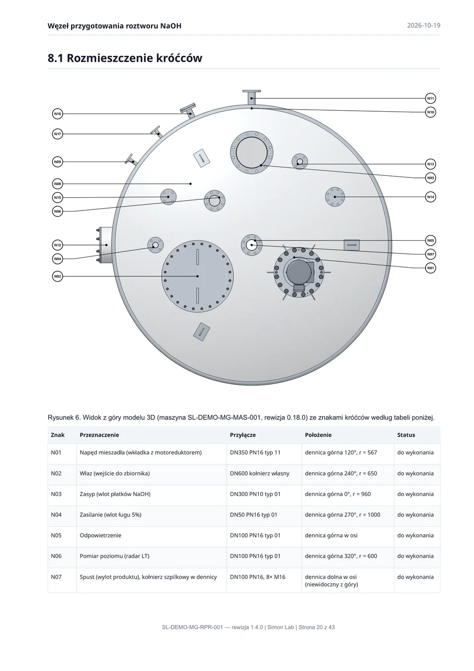
The machine from MechGraph and the cabinet from IonGrid arrive in PlantMesh, where the unit is assembled with its steelwork, platforms, piping and the people who will operate it.
Assembly
Converging into a process unit
Columns and beams, the bag-dump deck, the bucket elevator, the pump and the piping are placed around the tank; the lines from the P&ID are drawn in 3D from nozzle to nozzle.

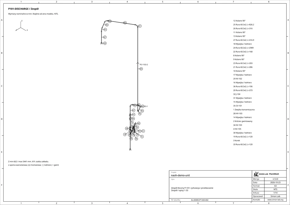
Isometrics
A drawing for every line
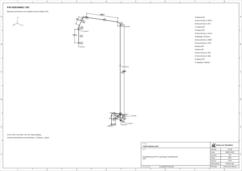
Each line gets its isometric with a parts list: here, the pump’s discharge line next to its sheet.
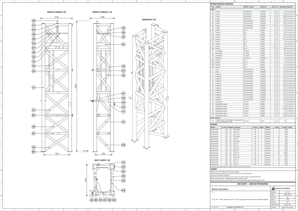
Steel
Structures with FEM, drawings from the model
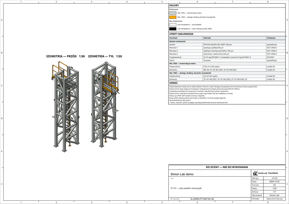
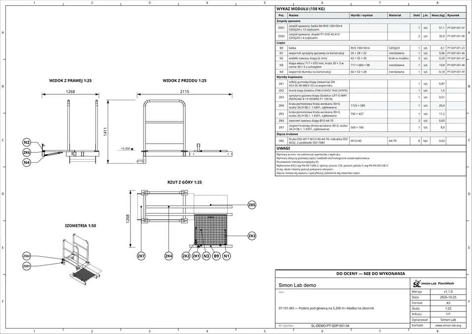
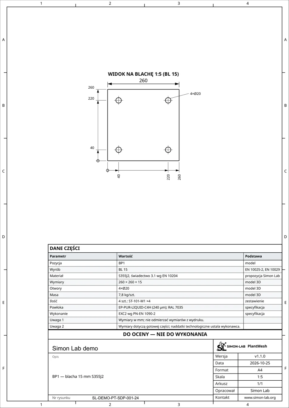
The support structures are checked with FEM analysis before their drawings are issued: here, the tower the operator stands on, next to its assembly drawing.
Clash detection
Found in the model, not on site
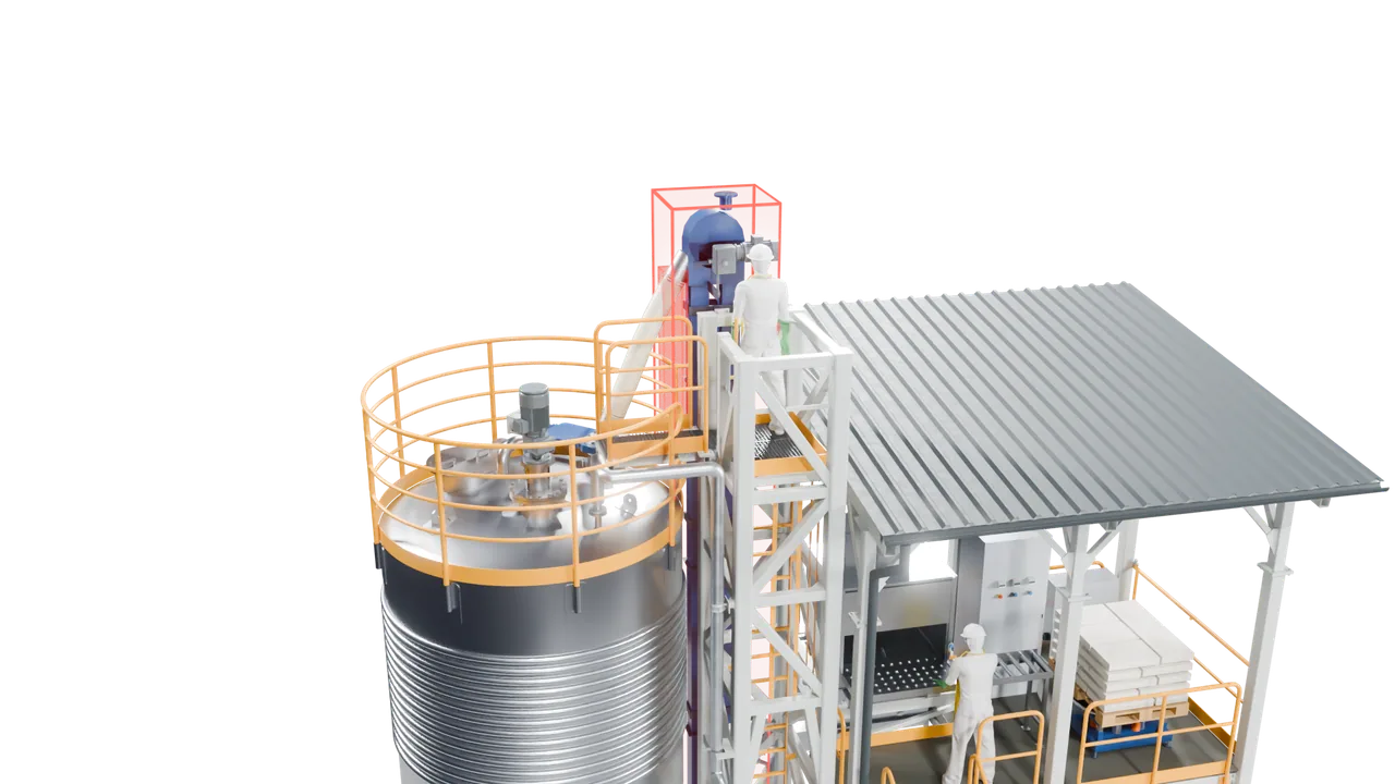
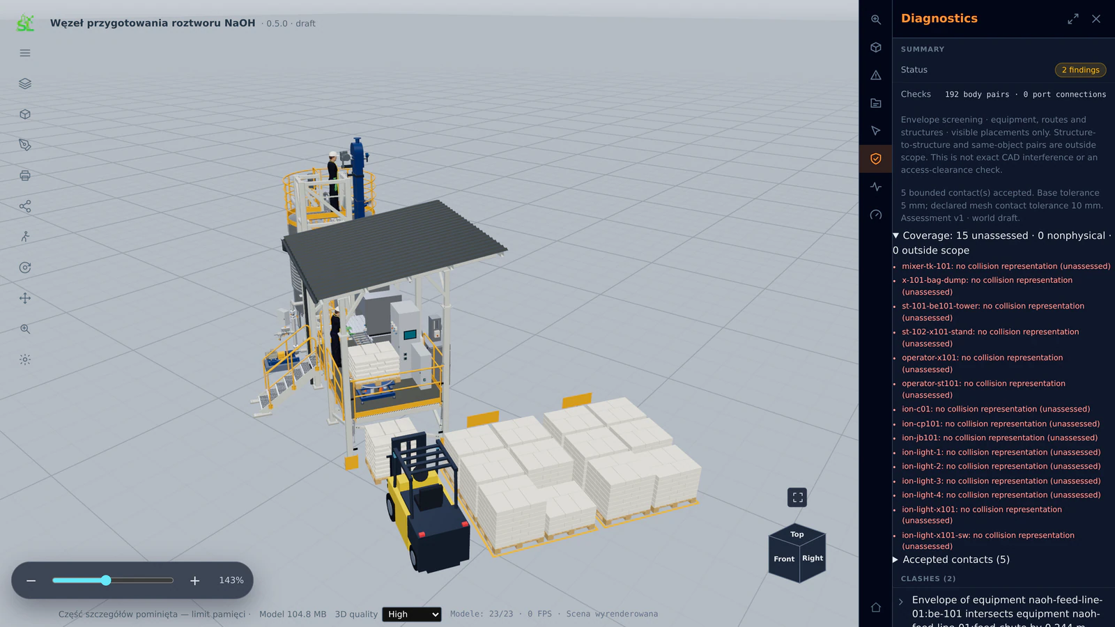
Automatic clash detection screens equipment, routes and structures against each other. In this unit it reports two findings: the envelope of the bucket elevator intersects its feed chute. That is exactly where such a finding belongs: on a screen, weeks before installation.
Layer 4 · Architecture
The unit in its plant
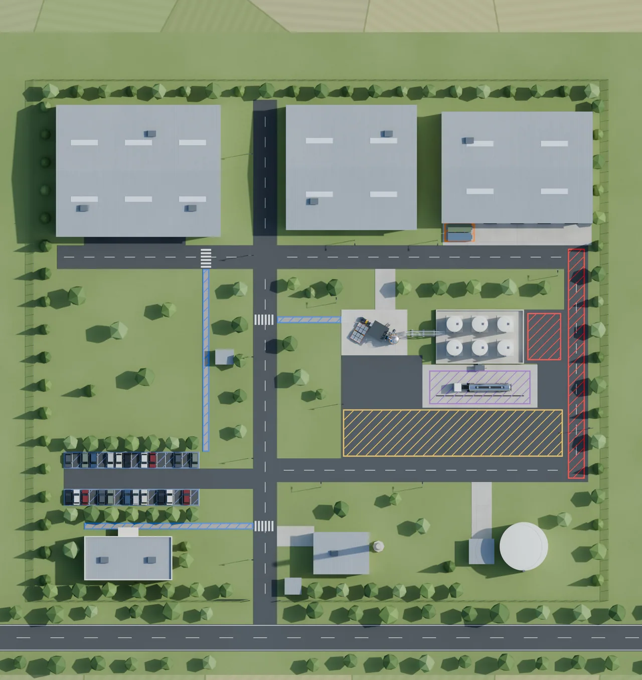
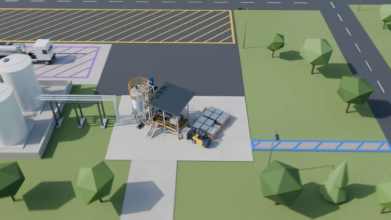
The prompt asked for a spare area of the plant. Architecture is where the unit leaves its own model and joins the site: terrain from public geospatial data, the roads and buildings around it, foundations under the tank legs, the access for tankers.
Site
From the unit to the plant
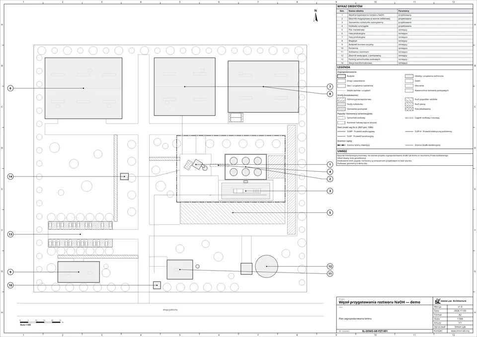
The unit takes the free corner the prompt asked for, and the questions change: what stands next to it (the tank farm with its bund, the unloading bay, the halls), how tankers reach it, and where traffic and storage are allowed. Architecture answers them in the same model.
Site plan
The drawing is the model
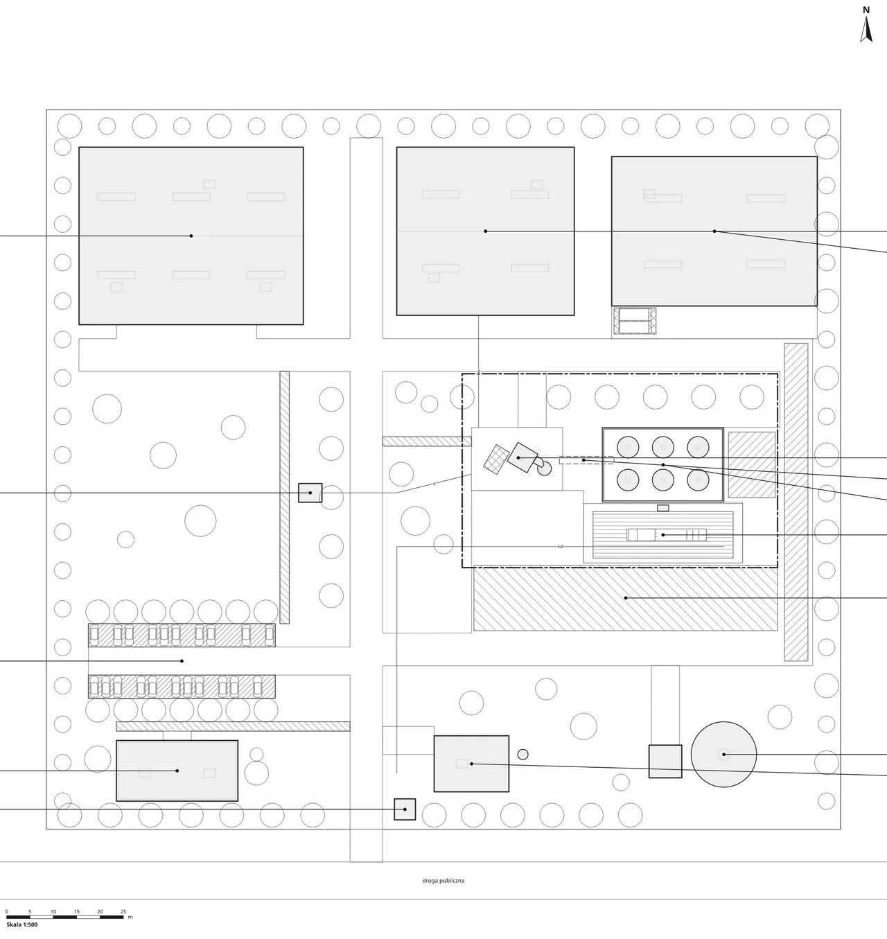
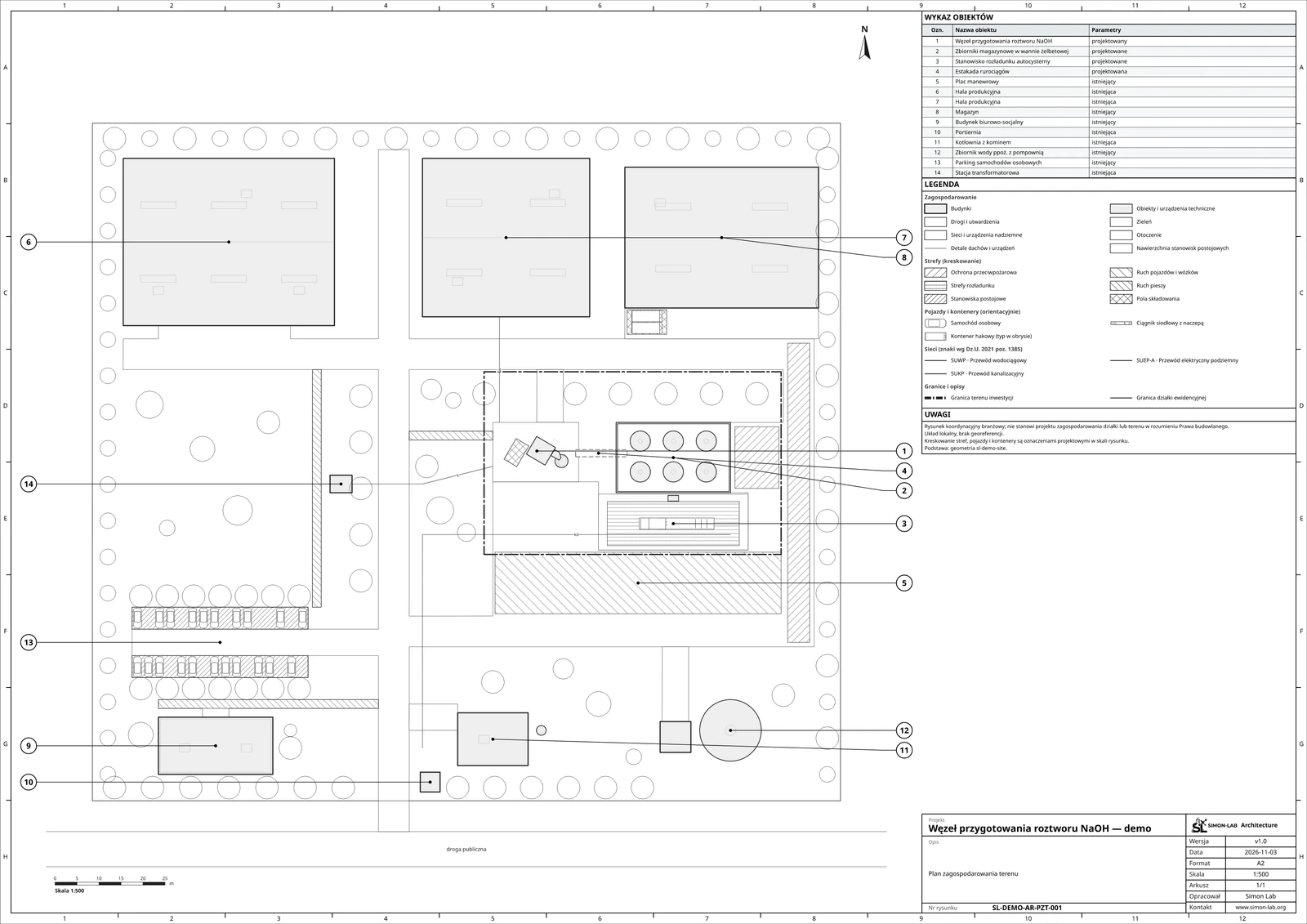
Seen from above, the same model becomes the site plan, drawn by the platform’s own renderer (buildings, zones, underground networks, the object list and the title block), so the drawing and the 3D scene cannot drift apart.
Output
A verified design package
Export
Construction-ready documentation
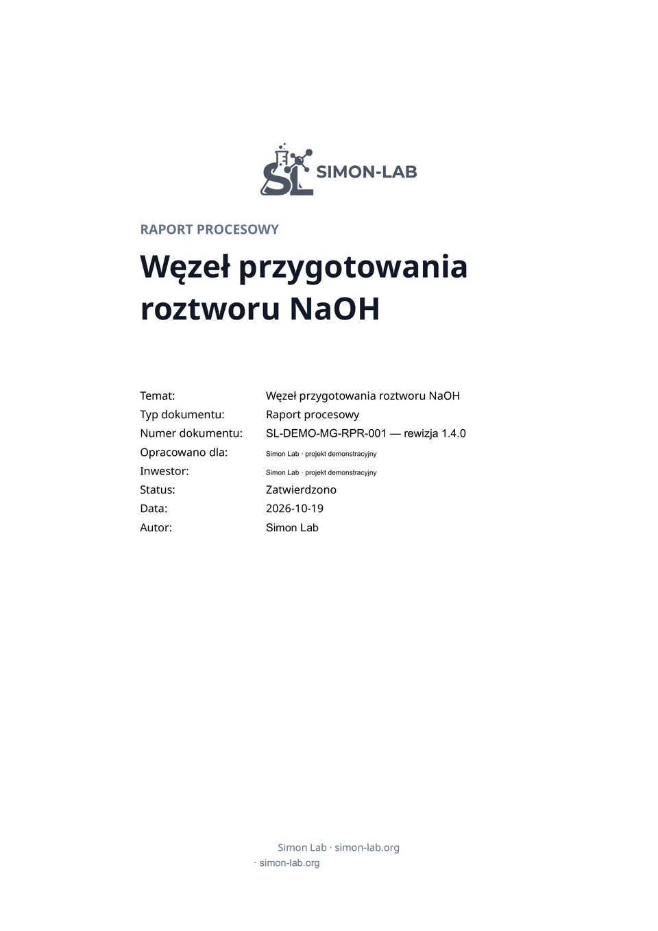
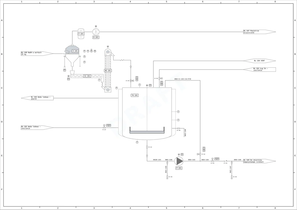
At the end, the layers are exported as documents: the P&ID, process and simulation reports, the mixer drawings, piping isometrics, structure and platform drawings, cabinet layouts and circuit diagrams, and the site plan. Each has its document number and revision, and each is a view of decisions made below it.
From a tested process and a clash-checked 3D model.
Under the hood
Rules, compute and an open architecture
An environment is only as good as what it can verify. Behind the applications, Simon Lab runs the machinery that turns an AI agent’s proposal into a checked result.
Rules
Good practice, written down
The rules of good engineering practice are part of the environment, not of the prompt: what must exist before the next layer may start, what every element must carry, which checks must pass. They are what steer an AI agent towards a complete project in the right order.
Compute
High-performance computing, included
CFD runs on dedicated compute nodes, FEM checks the structures, GPU rendering produces the visuals you have seen on this page, and AI-assisted CFD (Walrus, Gemini) speeds up the search through cases. Your AI agent does not need its own cluster.
Coming soon
Open source
We are opening the architecture: the way layers, rules and applications fit together will be published as open source, so others can build on the bottom-up method and run it in their own environments.
The film
Now in beta
Bottom-up chemical engineering, with trusted partners
Simon Lab is in beta with a small number of partners, one project at a time. If you are planning a unit, or building AI agents that should design one, we would like to hear from you.