Application suite

One application per discipline. One project underneath.

Each application covers one discipline of a plant project and reads what the previous ones decided, so the project stays consistent from the first specification to the last drawing. Documents are generated from the shared model.

Concept: the AI agent writes the specification
simon-lab · capacityindex agent · awaiting approval

Bring 5% lye to 30% with NaOH flakes from 25 kg bags, 14.5 m³ batch, max 60 °C in the tank, 40 °C at discharge. Design it with a bottom-up approach, layer by layer, and fit it into a spare area of my plant.

reading NaOH–H₂O thermodynamics…

balancing mass and heat of dissolution…

sizing agitation and cooling duty…

scanning the site for a spare plot…

drafting the design basis…

SPEC · NaOH dissolving unit · draft 1

DESIGN BASIS

product 30 % w/w NaOH · 14.5 m³ per batch

feed 5 % lye + NaOH flakes · 220 × 25 kg bags = 5.5 t per batch

handling bag-dump station · 2 bags/min · 25 kg within manual-handling limits

limits ≤ 60 °C in the tank · 40 °C at discharge

utilities chilled water 7.5 °C · half-pipe cooling jacket

vessel existing stainless tank · retrofit

PHYSICS FIRST

dissolution is exothermic → dosing rate bounded by cooling duty

density and viscosity 5 → 30 % from NaOH–H₂O property models

solids suspension and power number → agitator selection

CAPACITY & ECONOMICS

demand ≥ 60 m³ of lye per week · 3 shifts × 8 h · 7 days

lye fill and pump-out 10 m³/h each → one batch fits one shift

retrofit of the existing tank instead of a new vessel

LAYERS · bottom-up

4 Architecture spare area on site · roads · site plan

3 PlantMesh 3D assembly · isometrics · supports · clashes

2 MechGraph vessel · agitator · shaft · CFD

IonGrid control cabinets · I/O · heat gains

1 ProcessView P&ID · selections · dynamic simulation

0 CapacityIndex scope · capacity · economics ● this spec

OPEN POINTS

flake purity and size distribution: confirm with the supplier

dust extraction and empty-bag handling at the station

Illustration

Layer 0

CapacityIndex

Scope, capacity and economics

The investment-readiness cockpit and the project’s versioned scope. Capacity, economics, localization, permitting and risk become the specification every later layer builds on, and every change to it becomes a new version.

Open the CapacityIndex page
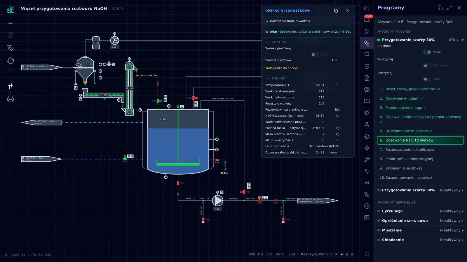
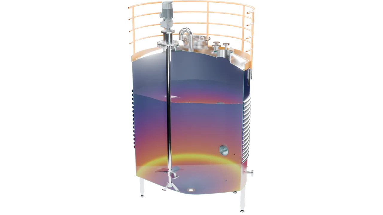
The simulation during dosing: NaOH flakes are added bag by bag while the chilled-water jacket takes away the heat of dissolution.

Layer 1

ProcessView

P&ID and dynamic process simulation

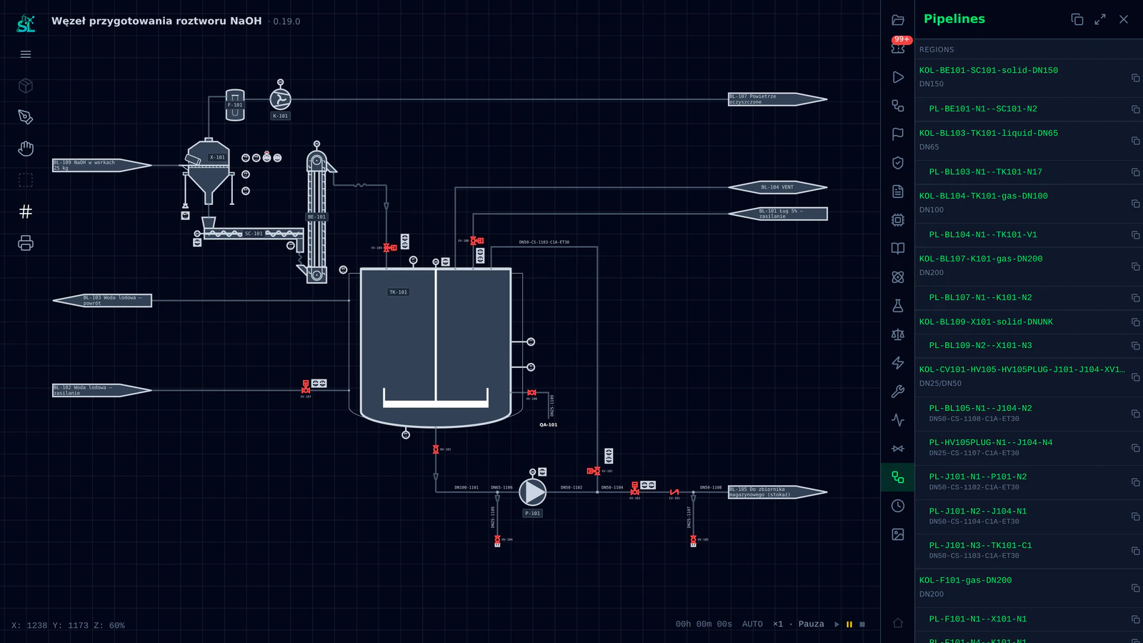
A web P&ID with an embedded physics simulation. Every line, valve and instrument carries its full selection, and ready-made control programs run on an emulated PLC, so the process is tested before anything is bought.

Open the ProcessView page
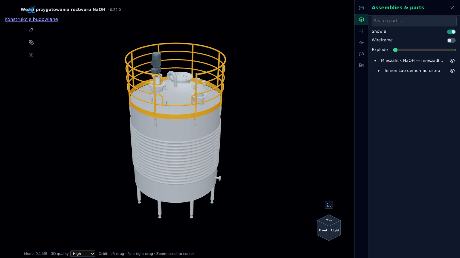
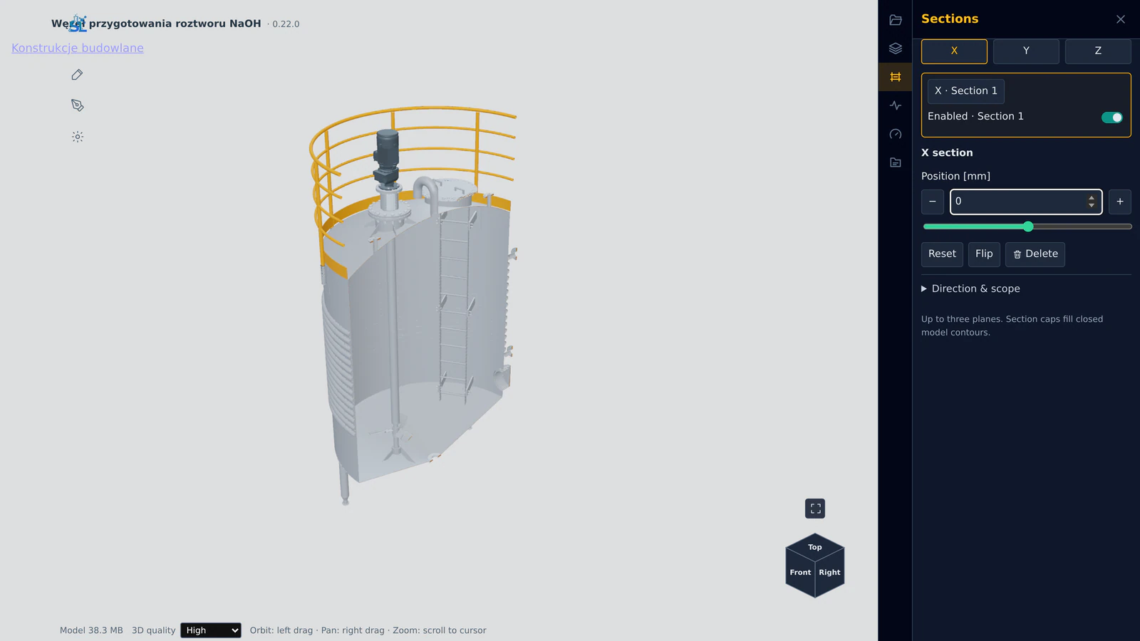
The MechGraph window in the dark canvas tone: the vessel with the agitator drive and the platform on its roof, and the Assemblies & parts panel with the machine’s assembly tree.

Layer 2

MechGraph

Machine design from dedicated calculations

Code-first engineering studies for process equipment: mixing power and solids suspension, shaft deflection and critical speed, strength and CFD. Reports and drawings are generated from the same model.

Open the MechGraph page
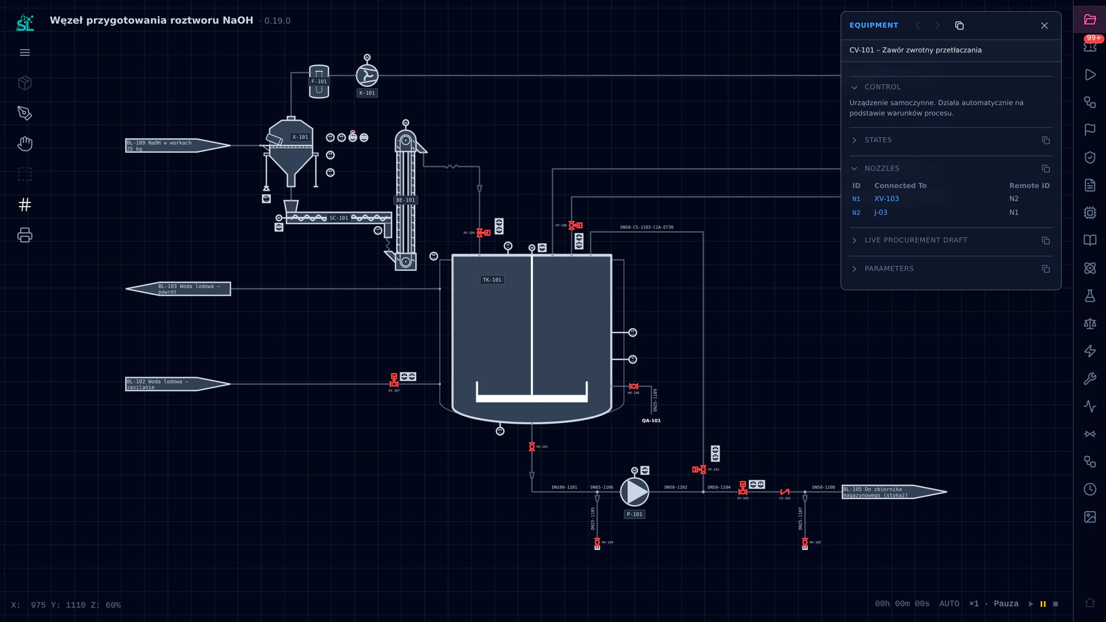
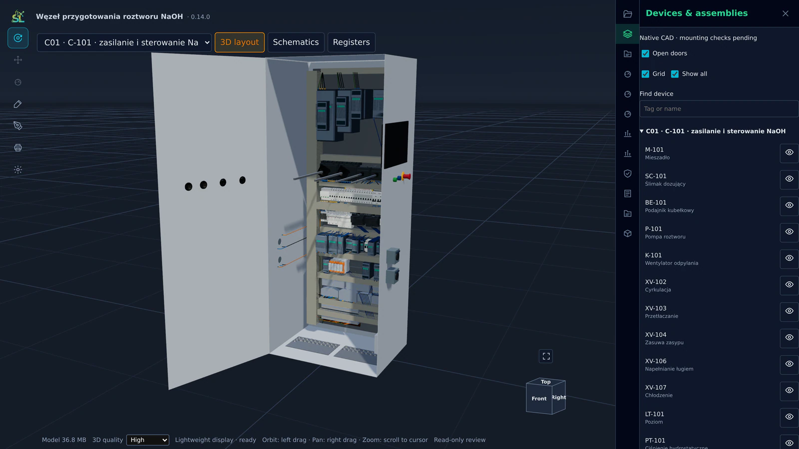
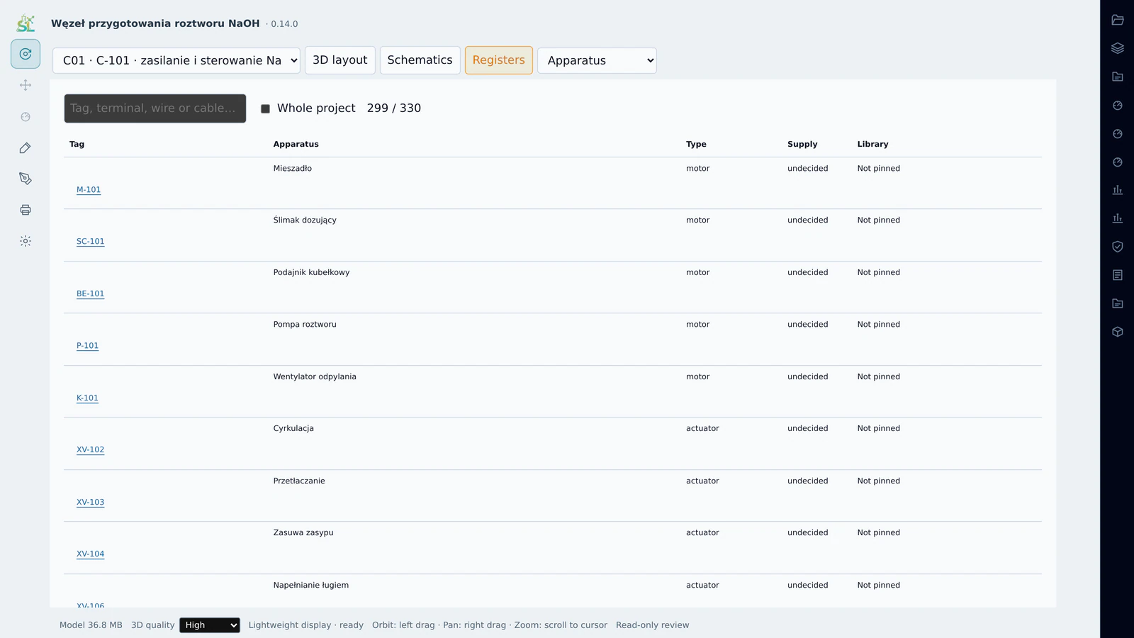
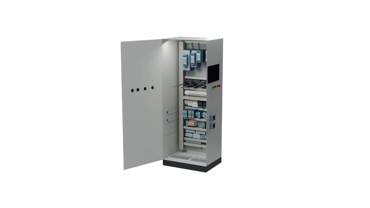
The IonGrid window in the dark canvas tone: the open control cabinet in 3D and the Devices & assemblies panel listing the devices it controls, from the agitator and the dosing screw to the valves and transmitters.

Layer 2

IonGrid

Control cabinets from catalogue components

In parallel with the machines, the control logic becomes real cabinets assembled from manufacturers’ catalogue models, with heat-loss data, pneumatic control and engineering registers.

Open the IonGrid page
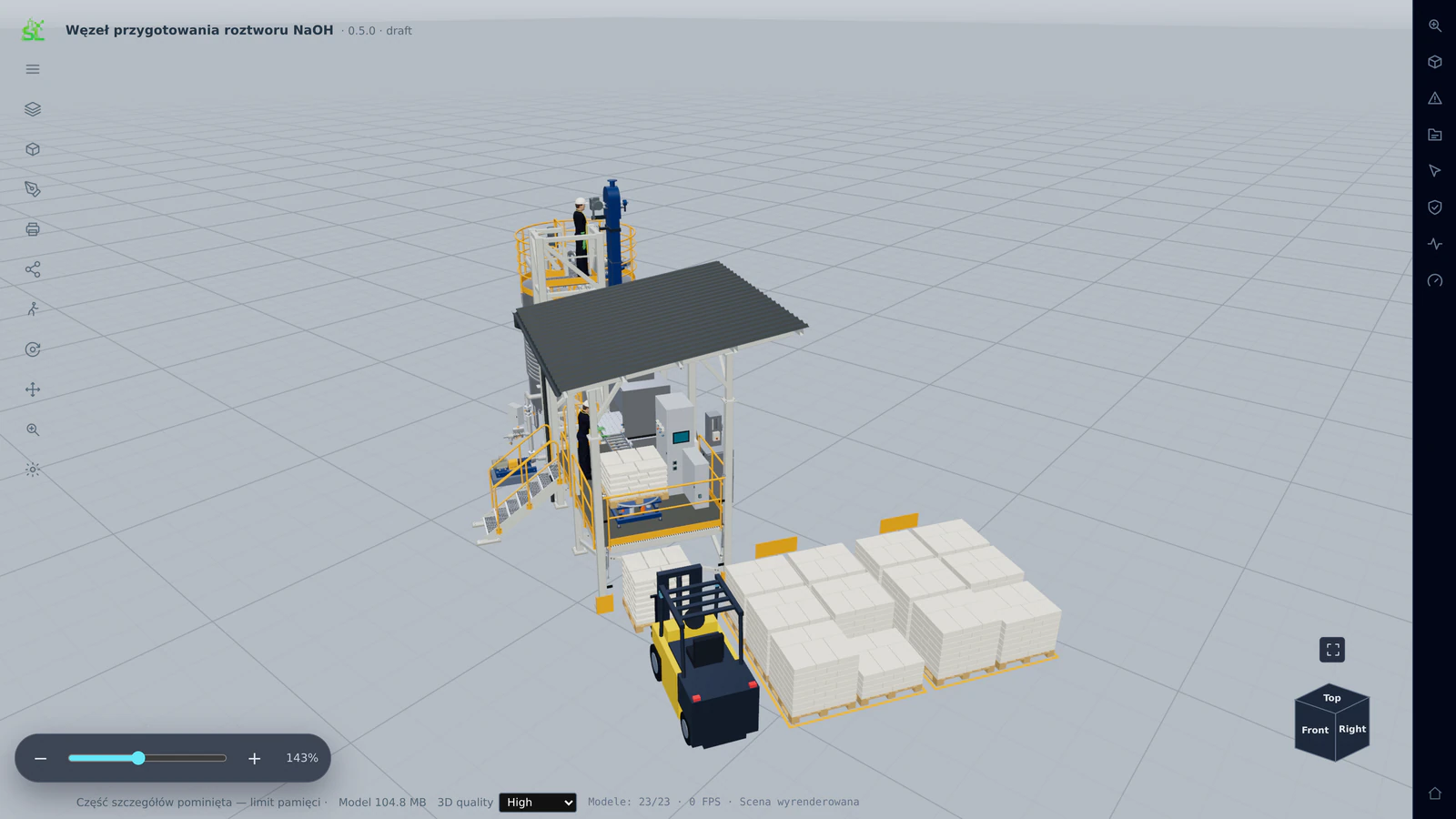
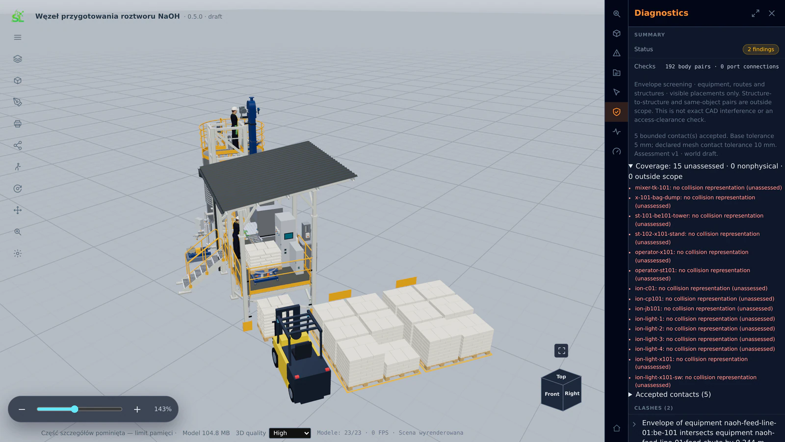
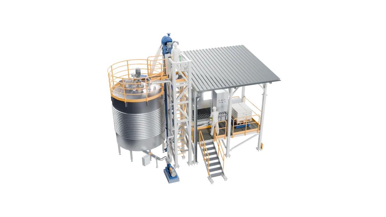
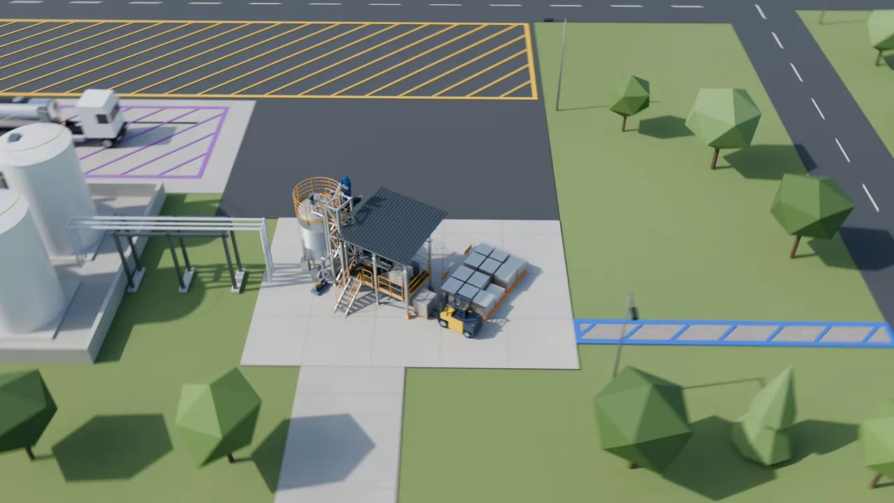
The PlantMesh window with the assembled unit.

Layer 3

PlantMesh

Process-unit assemblies in 3D

The machines and cabinets meet in one model: piping isometrics, support structures with FEM analysis, service access and automatic clash detection.

Open the PlantMesh page
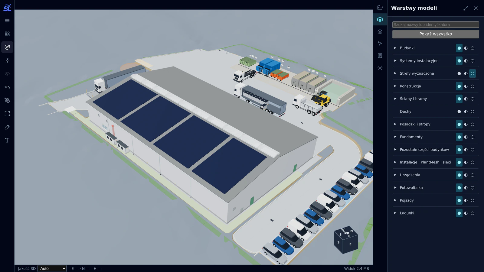
The federated BIM model of another project in Architecture: a production hall with photovoltaics on the roof, the staff car park, the truck unloading bay and container storage; the model layers panel lists buildings, structure, foundations, installations, photovoltaics and vehicles.

Layer 4

Architecture

The unit in its site

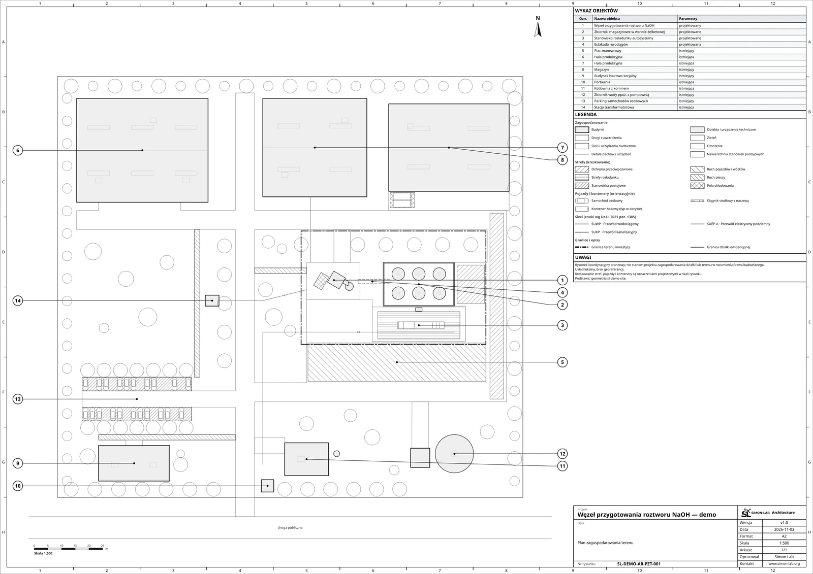
Georeferenced OpenBIM: terrain from public geospatial data, roads and buildings, IFC and 3D tiles, all the way to the site plan.

Open the Architecture page

The applications, in project order

  1. Beta

    CapacityIndex

    Scope, capacity and economics

    The investment-readiness cockpit and the project’s versioned scope. Capacity, economics, localization, permitting and risk become the specification every later layer builds on, and every change to it becomes a new version.

  2. Beta

    ProcessView

    P&ID and dynamic process simulation

    A web P&ID with an embedded physics simulation. Every line, valve and instrument carries its full selection, and ready-made control programs run on an emulated PLC, so the process is tested before anything is bought.

  3. Beta

    MechGraph

    Machine design from dedicated calculations

    Code-first engineering studies for process equipment: mixing power and solids suspension, shaft deflection and critical speed, strength and CFD. Reports and drawings are generated from the same model.

  4. Beta

    IonGrid

    Control cabinets from catalogue components

    In parallel with the machines, the control logic becomes real cabinets assembled from manufacturers’ catalogue models, with heat-loss data, pneumatic control and engineering registers.

  5. Beta

    PlantMesh

    Process-unit assemblies in 3D

    The machines and cabinets meet in one model: piping isometrics, support structures with FEM analysis, service access and automatic clash detection.

  6. Beta

    Architecture

    The unit in its site

    Georeferenced OpenBIM: terrain from public geospatial data, roads and buildings, IFC and 3D tiles, all the way to the site plan.

Coming soon

Free tools